This system is advantageous in that minor performance upgrades such as headers, intake manifold throttle bodies, etc. do not require a complete ECU recalibration since the flow meter will keep providing the ECU with air flow values. The drawback to this system is that engine performance is constricted to the size of the meter which limits the amount of air that can pass into the engine.
A third method to determine a value for the mass of air entering an engine is called a Speed Density System. The ECU in this system primarily relies on the input from a manifold absolute pressure sensor (MAP) which simply measures the vacuum and pressure levels in the intake manifold. The map sensor’s signal to the ECU is directly proportional to the load on the engine. Thus, between the MAP information and inputs from engine speed, throttle position, temperature and oxygen sensors, the ECU can look in a table and find a value of how much fuel should be injected based on all those sensor inputs.
Speed Density Systems are well suited for performance applications since their air induction is not limited to the size of an air flow meter. A drawback to this system is if there is a significant increase in the performance of the powertrain, the ECU must have a new set of fuel calibration tables which in some cases calls for an all new ECU.
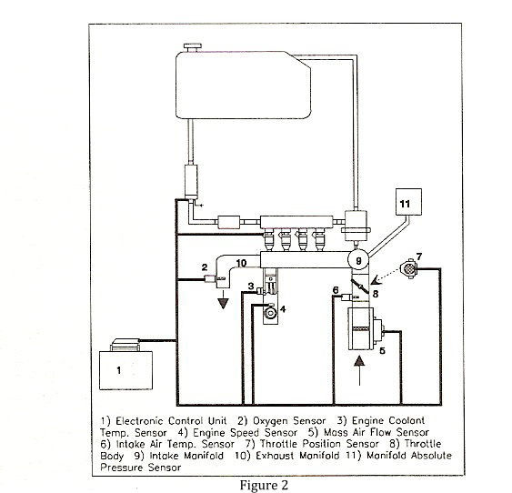
As one can imagine, with the advent of computer power, the auto companies are steadily increasing the sophistication and complexity of electronic fuel injection. Nevertheless, almost all Multi-Port Systems are similar to that shown in Figure 2 (non-returnless system shown).
Data Processing/Fuel Metering System
The actual processing of the information that occurs in the cells of the ECU is beyond the scope of this article. In simple terms, the ECU has a series of data tables programmed into its memory which list a value of all the sensors, the ECU will look in the tables and match the sensor values with the proper fuel value. This value should produce an air to fuel ratio of approximately 14.7:1, called stoichemetric.
Fuel is metered through fuel injectors by pulsing their internal valves to open and close at an extremely rapid pace measured in milliseconds (ms). The ECU is constantly updating the fuel injector’s open to close time, known as the pulse width (PW) and the time between pulses, known as the pulse interval (PI). As the engine demand for fuel increases, the sensors relay that requirement to the ECU, which looks in the tables for the corresponding injector pulse width and pulse interval to meet the demand. In general, the ECU will increase PW and decrease PI to richen the fuel mixture and as well decrease PW and increase PI to lean the mixture. This way the ECU can infinitely adjust the fuel flow to match engine demand under any possible condition and at any point in time.


