Fuel Injectors
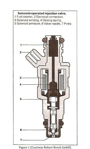
A fuel injector is basically an electronic solenoid valve which, when activated, allows pressurized fuel to escape through a nozzle. The fuel injector primarily consists of an armature coil and a needle valve (see Figure 1). With the absence of current to the coil winding, the needle valve is forced against the metering orifice (the injector’s outlet) by a spring. When the ECU sends a current pulse to the injector coil, the winding is energized which creates a magnetic force strong enough to pull on the steel needle valve uncovering the orifice and allowing fuel to pass. Once the current at the coil is turned off, the internal spring slams the valve shut cutting off the fuel flow.
Generally, the fuel flow is metered at the injector’s tip by a precisely machined orifice. The injector’s flow rate is determined by the relationship of the orifice size and the configuration of the needle valve. This relationship is extremely critical for some injector designs where the needle valve’s tip actually protrudes through the orifice even when the valve is pulled completely off its seat. This tip, called a pintle, is used to help atomize the fuel spray.
This valve-orifice design does not produce a variable flow rate. The fuel that passes through the orifice is constant. The valve just turns the flow on and off. So how is the flow rate increased or decreased to meet engine demand? The ECU controls the on-off time of the injectors. The ECU sends short, rapid current pulses to the injectors that are so fast they are measured in milliseconds. Short current pulses with long pulses in between each pulse will inject less fuel into the cylinders over a given time period than long pulses with short pauses over the same time period. Therefore, the ECU can vary the injector flow rate to meet engine demand.
